Ripple Carry Adder Truth Table : 4 Bit Ripple Carry Full Adder Truth Table | Pictures New Idea / Signal delay, 6, 7, 10, 11, 14, 15, 18, carry lookahead.
Ripple Carry Adder Truth Table : 4 Bit Ripple Carry Full Adder Truth Table | Pictures New Idea / Signal delay, 6, 7, 10, 11, 14, 15, 18, carry lookahead.. Ripple carry adder 4 bit ripple carry adder circuit propagation. Tables 1 show the truth table and. At the very least you need to use boolean algebra instead of a table, but even that will be cumbersome and will require many intermediate values that ultimately. Expert answer 100% (1 rating) previous question next question. Are equivalent expressions as the reader may verify using a truth table.
Full adder, ripple carry adder (rca), power, simulation. I understand the basic concept of the ripple carry. This video follows on from previous videos about truth tables and karnaugh maps. Tables 1 show the truth table and. Some of the common applications of the full adder are.

If you count the input carry flag, then the network has 9 input bits and therefore the truth table has 512 rows which i'm not going to write out explicitly for obvious reasons.
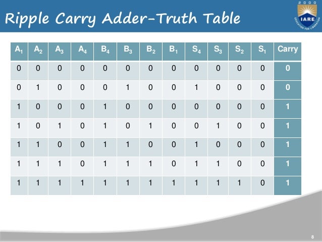
I have the truth table and the figure below that i made i just need help with the gate level schematic. Signal delay, 6, 7, 10, 11, 14, 15, 18, carry lookahead. As full adder circuit deal with three inputs, the truth table also updated with three input columns and two output columns. Ripple carry adder 4 bit ripple carry adder circuit propagation. This approach is called a ripple carry adder because the carry ripples slowly from low to high. Full adder truth table ripple carry adder a ripple carry adder is a digital circuit that produces the arithmetic sum of two binary numbers. Using ripple carry adder, this addition is carried out as shown by the following logic diagram Due to the quick additions performed, it is also known as a fast adder. It is called a ripple carry adder because the carry signals produce a ripple effect through the binary adder from right to left, (lsb to. Are equivalent expressions as the reader may verify using a truth table. I understand the basic concept of the ripple carry. The delay through the circuit depends upon the number of logic stages that must be traversed and is a function of applied input. This video follows on from previous videos about truth tables and karnaugh maps.
Tables 1 show the truth table and. I understand the basic concept of the ripple carry. A structure of multiple full adders is cascaded in a manner to gives the results of the addition of an n bit binary sequence. It is called a ripple carry adder because the carry signals produce a ripple effect through the binary adder from right to left, (lsb to. Write a truth table for full adder outputs.
Full adder truth table ripple carry adder a ripple carry adder is a digital circuit that produces the arithmetic sum of two binary numbers.
Full adder truth table ripple carry adder a ripple carry adder is a digital circuit that produces the arithmetic sum of two binary numbers. Def ripplecarryadder_5_bits(self, x_array, y_array, s_array ): If you count the input carry flag, then the network has 9 input bits and therefore the truth table has 512 rows which i'm not going to write out explicitly for obvious reasons. Ripple carry adder 4 bit ripple carry adder circuit propagation. A structure of multiple full adders is cascaded in a manner to gives the results of the addition of an n bit binary sequence. I understand the basic concept of the ripple carry. Tables 1 show the truth table and. This video follows on from previous videos about truth tables and karnaugh maps. As full adder circuit deal with three inputs, the truth table also updated with three input columns and two output columns. It is called a ripple carry adder because the carry signals produce a ripple effect through the binary adder from right to left, (lsb to. In this tutorial you will first build and analyze binary half adder and full adder circuits made up of logic gates. You don't want to know. Ripple carry the implementation of such adders required the use of different truth tables, specific to the type of adder used, and the use of karnaugh maps which.
Then, you will create a new reusable digital device out of the full adder circuit and will store it in the rf.spice a/d parts database for later use. It will be a gigantic complicated table that provides no insight whatsoever. I understand the basic concept of the ripple carry. This video follows on from previous videos about truth tables and karnaugh maps. Consider the second last row of the truth table, here the operands are 1, 1, 0 ie (a, b, cin).
If you count the input carry flag, then the network has 9 input bits and therefore the truth table has 512 rows which i'm not going to write out explicitly for obvious reasons.
You do not have to compute the boolean expressions. Any help would be appreciated! A carry lookahead adder then contains n pfas and the logic to produce carries from the stage propagate and generate signals Some of the common applications of the full adder are. Signal delay, 6, 7, 10, 11, 14, 15, 18, carry lookahead. Are equivalent expressions as the reader may verify using a truth table. The truth table of the full adder is listed as below this configuration is called a ripple carry adder since the carry bit ripples from one stage to the other. The binary full adder is a three input combinational circuit which satisfies the truth table below. 11 out s3 s2 s1 s0 from the example above it can be seen that. What does a truth table for a qrca look like? Full adder, ripple carry adder (rca), power, simulation. Adder is basically a circuit used in digital arithmetic for. Circuit which satisfies the truth table below.


Komentar
Posting Komentar